Pico: UART serial with MicroPython, talking to other chips
Wire two devices with TX, RX, and a common ground. Read a GPS module, talk to a Nextion display, or exchange data between two Picos over UART in MicroPython.
UART is the oldest serial protocol still in use, and it is the one you will reach for most often when you need a microcontroller to talk to another chip. GPS modules, RFID readers, Nextion displays, ESP8266 modules, even another Pico, all use UART. Two wires, a common ground, and a baud rate.
This is the tutorial I wish I had read before wiring a GPS module up wrong twice. The thing I got wrong: the TX of one device goes to the RX of the other, not to the TX of the other. Every beginner gets this once.
What you need
- Raspberry Pi Pico (or Pico W)
- Another UART device (a GPS module, an Arduino, a second Pico, a Nextion display, an ESP8266)
- 3 jumper wires (TX, RX, GND)
- USB cable
- MicroPython firmware installed (see below)
For the GPS example I use the common NEO-6M module. For a Pico talking to a Pico, you need two Picos. For a Nextion, any of the basic 2.4” or 3.2” displays.
Install MicroPython
Hold the BOOTSEL button on the Pico while plugging in the USB
cable. The Pico appears as a USB drive. Drag the
RPI-PICO-2024-...uf2 file from
https://micropython.org/download/RPI_PICO/ onto the drive. The
Pico reboots as a MicroPython device.
To talk to the REPL, use Thonny (pip3 install thonny) or
mpremote (pip3 install mpremote). Both work. Thonny is more
beginner-friendly; mpremote is the CLI option I use.
Wiring
The Pico has two UART peripherals: UART0 and UART1. The default pin mapping is:
UART0 TX = GP0  (physical pin 1)
UART0 RX = GP1  (physical pin 2)
UART1 TX = GP4  (physical pin 6)
UART1 RX = GP5  (physical pin 7)
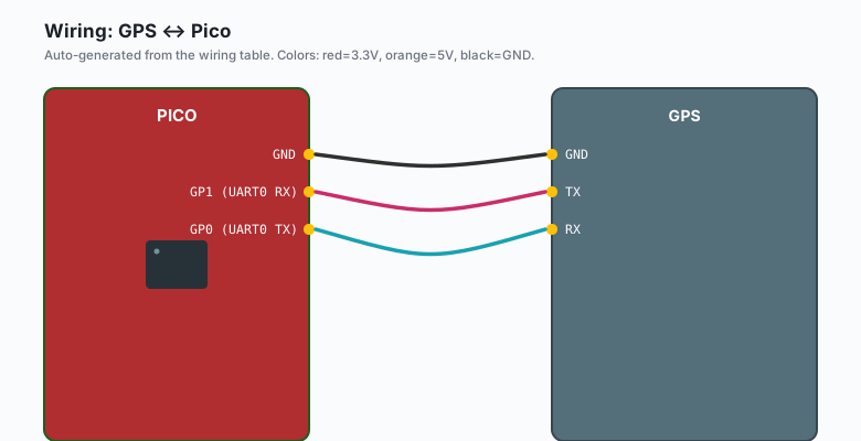
For a GPS module:
GPS VCC -- Pico 3.3V (the NEO-6M is 3.3V)
GPS GND -- Pico GND
GPS TX  -- Pico GP1 (UART0 RX)
GPS RX  -- Pico GP0 (UART0 TX)
Notice the cross: the GPS’s TX goes to the Pico’s RX (GP1), and the GPS’s RX goes to the Pico’s TX (GP0). The rule is always “my TX to your RX.” If both devices try to drive the same wire, nothing works.
The “common ground” requirement is the third wire. Both devices need to share a ground reference, or the voltage levels do not mean anything. With separate power supplies (e.g. a Pico on USB and a GPS on a battery), the ground wire is what ties them together.
The code
from machine import UART, Pin
import time

uart = UART(0, baudrate=9600, tx=Pin(0), rx=Pin(1))

while True:
    if uart.any():
        data = uart.read()
        if data:
            print(data)
    time.sleep(0.1)
That is the entire pattern for receiving. UART(0, ...) is the
UART0 peripheral. baudrate=9600 is the speed in bits per
second. The tx and rx arguments set the GPIO pins.
uart.any() returns the number of bytes waiting in the receive
buffer. If it is greater than zero, there is data to read.
uart.read() reads whatever is in the buffer and returns it as
a bytes object.
The GPS at 9600 baud emits one sentence per second, so the loop above catches them.
Baud rates: 9600, 115200, 921600
Baud rate is the speed of the serial link in bits per second. The two devices have to agree, or the data is garbage.
Common rates and what uses them:
- 9600: the default for most GPS modules, RFID readers, and older serial devices. Slow but universal.
- 115200: the default for ESP8266 AT firmware, Nextion displays, and most modern dev boards. 12x faster than 9600.
- 921600: the high-speed option for short-range links. Some sensors go this fast; some go to 1 Mbaud or higher.
Higher baud rates need shorter wires. At 9600, a 1-meter wire is fine. At 921600, keep it under 30 cm or you get signal integrity issues.
Pick the lowest baud rate the device supports. Faster is not better if the device cannot keep up.
Reading GPS data
A GPS module at 9600 baud sends NMEA sentences, one per second:
$GPGGA,123519,4807.038,N,01131.000,E,1,08,0.9,545.4,M,46.9,M,,*47The MicroPython code to parse this is straightforward:
import time

def parse_gga(sentence):
    if not sentence.startswith('$GPGGA'):
        return None
    parts = sentence.split(',')
    if len(parts) < 10 or not parts[2] or not parts[4]:
        return None
    return {
        'time': parts[1],
        'lat': float(parts[2][:2]) + float(parts[2][2:]) / 60,
        'lat_dir': parts[3],
        'lon': float(parts[4][:3]) + float(parts[4][3:]) / 60,
        'lon_dir': parts[5],
        'fix': int(parts[6]),
        'sats': int(parts[7]),
    }

uart = UART(0, baudrate=9600, tx=Pin(0), rx=Pin(1))
buf = b''
while True:
    if uart.any():
        buf += uart.read()
        if b'\n' in buf:
            line, _, buf = buf.partition(b'\n')
            sentence = line.decode('utf-8', 'ignore').strip()
            fix = parse_gga(sentence)
            if fix and fix['fix']:
                print(f"Lat {fix['lat']:.4f} {fix['lat_dir']}, "
                      f"Lon {fix['lon']:.4f} {fix['lon_dir']}, "
                      f"{fix['sats']} sats")
    time.sleep(0.05)
The buffer accumulates bytes until a newline arrives, then the
sentence is parsed. NMEA sentences end with \r\n. The checksum
(star *47 at the end) is optional to verify.
Hardware flow control (RTS/CTS)
Most UART links do not need flow control. The receiver is fast enough, the buffer is big enough, and data does not back up.
For high-speed or high-volume links, you can add RTS (Request To Send) and CTS (Clear To Send) pins. The receiver drops RTS when its buffer is full, the sender sees CTS go high and stops sending. This prevents data loss.
In practice, the only UART devices I have used that need hardware flow control are: Bluetooth modules at high baud rates, some industrial sensors, and ESP8266 AT firmware when streaming. For a GPS, RFID, Nextion, or Pico-to-Pico link, software flow control (XON/XOFF) or no flow control works.
To enable flow control on the Pico:
uart = UART(0, baudrate=115200,
            tx=Pin(0), rx=Pin(1),
            rts=Pin(2), cts=Pin(3))
You also need to wire the RTS/CTS pins between the two devices.
The UART1 / UART0 distinction on Pico (GPIO mapping)
The Pico has two UART peripherals. UART0 is on GP0/GP1 by default. UART1 is on GP4/GP5. You can move them to other pins with the constructor:
# UART1 on GP8 (TX) and GP9 (RX)
uart = UART(1, baudrate=115200, tx=Pin(8), rx=Pin(9))
This is useful when you want to use the REPL on UART0 and a sensor on UART1. The REPL uses UART0 by default, and you do not want to share that with a GPS spamming sentences every second.
You can have both UART0 and UART1 running at the same time:
import sys
uart0 = UART(0, baudrate=115200, tx=Pin(0), rx=Pin(1))
uart1 = UART(1, baudrate=9600, tx=Pin(8), rx=Pin(9))
The REPL keeps using UART0 (USB serial), and you can use the physical pins for your own purposes. Or you can move UART0 to different pins if you need GP0/GP1 for something else (e.g. I2C).
When to use UART vs I2C vs SPI
The three serial protocols for inter-chip communication, and when to pick each:
- UART: 2 wires (TX, RX), one device per UART peripheral, no addressing, simple. Use for: GPS, RFID, Bluetooth modules, Nextion displays, anything that streams data.
- I2C: 2 wires (SDA, SCL), many devices on the same bus with addresses, 400 kHz fast mode, 3.4 MHz on Pico. Use for: sensors (BME280, MPU6050, OLED), GPIO expanders, anything with a register map.
- SPI: 4+ wires (MOSI, MISO, SCK, CS), one device per CS pin, very fast (tens of MHz). Use for: SD cards, displays with high refresh, sensors that need fast reads (e.g. thermal cameras).
The decision tree: if the device streams a lot of data and you need speed, SPI. If the device has many registers and a few control lines, I2C. If the device is a module that speaks a simple protocol (GPS, RFID, Bluetooth), UART.
When something breaks
- Garbage characters on the serial monitor. Baud rate mismatch. The two devices are speaking at different speeds. Check the datasheet, set both to the same rate.
- No data at all. TX/RX are swapped. Swap them.
- Intermittent garbage. Bad ground. Make sure both devices share a ground wire, especially if they have separate power supplies.
- Pico crashes when GPS is plugged in. Voltage mismatch. The NEO-6M is 3.3V, but if you accidentally power a 5V device from the Pico’s 3.3V, or vice versa, the chip can latch up. Add a level shifter if needed.
uart.any()always returns 0. The device is not transmitting, or you are on the wrong UART. Try the other UART. Check that the device is actually powered (its LED should be on, or its output pin should be high).
What to build next
- A GPS logger that writes coordinates to an SD card every second.
- A Nextion display that shows the value of a sensor (covered in the display tutorial).
- A Pico-to-Pico link that sends a message every second (the basic serial chat pattern).
- A Bluetooth bridge: pair an HC-05 module to a phone, forward UART data over Bluetooth.
The Nextion display tutorial is the natural next project. The Pico-to-Pico chat is a quick 10-minute build you can use as a test bed for the rest. The book Pico MicroPython has a chapter on building a sensor hub that reads a dozen sensors over UART and I2C, then streams the combined data over a single UART link to a Raspberry Pi.