Pico: measure wind speed with an anemometer
Wire a cup anemometer's reed switch to a Pico, count pulses with an interrupt, and convert pulse rate to wind speed with the manufacturer's constant.
The cup anemometer is the sensor that makes wind real: three cups on a rotor, spinning faster as the wind picks up. Inside the hub, a magnet sweeps past a reed switch once per rotation, and every pass closes a contact for a few milliseconds. Your job is to count closures and divide by time. No ADC, no protocol, no library. It is the cleanest interrupt lesson on any microcontroller, because the pulses arrive slowly enough to see and fast enough to matter.
The trap is polling. I read the reed switch in a while True loop
with a sleep, and missed gusts all afternoon, because a single
time.sleep(1) between reads will swallow two or three pulses at a
decent breeze. A pulse arriving while you sleep does not queue up. It
just never happened, as far as your program is concerned. The fix is a
hardware interrupt on the GPIO pin, which counts edges even while the
main loop is doing something else (e.g. writing to the SD card in the
datalogger version at the end).
The second trap is contact bounce. A reed switch is a mechanical contact, and a mechanical contact does not close once. It closes, bounces open and shut for a millisecond or two, then settles. Without debouncing, one rotation counts as three. The MicroPython fix is a time check inside the interrupt handler: ignore any pulse that arrives within 10 ms of the last one. At 10 ms, a rotor spinning at 600 rpm (one pulse every 100 ms minimum, faster than any wind this switch survives) still counts every pulse honestly.
What you need
Needed
- Raspberry Pi Pico (or Pico W), about $4-6.
- Cup anemometer with reed-switch output. Two common picks:
- The “SPG-30” style plastic cup anemometer with 2-core cable (about $15), which is what most DIY weather kits ship.
- A Davis Instruments 6410 or a spare Vantage Pro anemometer (about $40), if you want the thing that survives actual storms.
- 2-core outdoor cable or two jumper wires, if the sensor does not already have a lead.
Nice to have
- Pole mount (a 1 inch PVC pipe section plus a hose clamp works).
- Weatherproof junction box or cable gland, for a permanent install.
- Soldering iron + solder, if the sensor’s cable needs attaching to the terminal block.
- Soldering iron stand, for parking the hot iron.
- Helping hands, for holding the cable while tinning.
- Anti-static wristband, for handling the bare Pico.
- Magnifying goggles, for reading the tiny terminal labels.
- Soldering mat, to keep resin off the bench.
- Wire stripper, for the 2-core cable ends.
- Multimeter, to watch the switch close by hand before coding.
Wiring
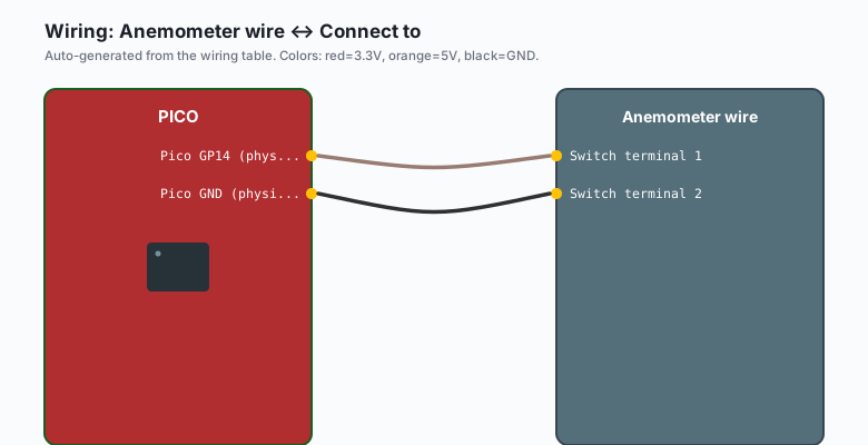
The reed switch is just a switch: two terminals, no polarity. One side to a GPIO pin, the other to ground, and the internal pull-up does the rest.
| Anemometer wire | Connect to |
|---|---|
| Switch terminal 1 | Pico GP14 (physical pin 19) |
| Switch terminal 2 | Pico GND (physical pin 18, any GND) |
That is the entire circuit. No resistor, no external pull-up: the
Pin.PULL_UP in the code holds the input high, and each switch
closure pulls it to ground.
Keep the signal wire away from long runs next to motors or mains cable. A reed switch contact is a plain open circuit when idle; it can pick up noise on a 10-meter unshielded run. Twisted pair or a shielded cable fixes it if your pole is tall.
Install
No libraries. Everything is in the standard MicroPython firmware
(machine.Pin, machine.Timer). If you have not flashed MicroPython
yet, the Pico MicroPython setup tutorial covers it: hold BOOTSEL
while plugging in USB, drag the UF2 file onto the drive that appears.
The code
The pulse counter runs in an interrupt; the main loop reads the count once per second and applies the conversion factor.
from machine import Pin, Timer
import time

# ---- config --------------------------------------------------------
ANEM_PIN = 14          # GP14, physical pin 19
# pulses per second -> wind speed. Every manufacturer publishes one.
#   1 pulse/sec = 1.492 mph is the classic Inspeed/Vantage constant.
#   Check your datasheet. Wrong constant = confidently wrong data.
PULSE_TO_MPH = 1.492
DEBOUNCE_MS = 10       # ignore pulses closer than this

# ---- state (touched by the IRQ handler only) -----------------------
pulse_count = 0
last_pulse_ticks = 0

def wind_isr(pin):
    # Runs with interrupts disabled; keep it tiny
    global pulse_count, last_pulse_ticks
    now = time.ticks_ms()
    if time.ticks_diff(now, last_pulse_ticks) < DEBOUNCE_MS:
        return            # bounce: not a real rotation
    last_pulse_ticks = now
    pulse_count += 1

# Reed switch to GND, pull-up holds it high, falling edge = a rotation
anem = Pin(ANEM_PIN, Pin.IN, Pin.PULL_UP)
anem.irq(trigger=Pin.IRQ_FALLING, handler=wind_isr)

# ---- main loop: report once per second ----------------------------
report = Timer()

def tick(timer):
    global pulse_count
    # Critical section: swap the count out so the ISR keeps counting
    state = machine.disable_irq()
    pulses = pulse_count
    pulse_count = 0
    machine.enable_irq()

    mph = pulses * PULSE_TO_MPH
    # 1 pulse per reporting window is the resolution floor.
    # Longer windows smooth the gusts (e.g. 6 s windows = 0.25 mph steps).
    print(f"{pulses} pulse(s) this window -> {mph:.1f} mph")

report.init(period=1000, mode=Timer.PERIODIC, callback=tick)

while True:
    time.sleep(1)
Three things carry the design:
- The interrupt handler does one thing: bump a counter. No printing,
no floating-point math, no
sleepinside an IRQ. A handler that lingers freezes everything else (e.g. the Timer callback and any other IRQ on the chip). disable_irq()around the read-and-reset makes the read-modify-write atomic. Without it, a pulse landing betweenpulses = pulse_countandpulse_count = 0gets lost.- The conversion constant is per-model. The 1.492 mph constant is common but not universal; the datasheet number wins every time.
Converting pulses to speed
One pulse per rotation. Speed comes from the manufacturer’s pulses-per- mph constant, because cup anemometers are calibrated instruments, not just switches:
- Inspeed and most Davis clones: 1 pulse/s = 1.492 mph (2.4 km/h).
- Some generic units: 1 pulse/s = 1.0 m/s; check the sheet.
Resolution is limited by your reporting window. At one reading per second, the smallest nonzero reading is 1.492 mph. Averaging over a longer window divides that floor (e.g. six seconds per window gives quarter- mph steps and steadier gust numbers).
Gusts versus averages: keep both. Track the max over a rolling minute for the gust value and the mean over the same minute for the sustained value. A weather station that only reports the mean makes every storm look boring.
The calibration check
You do not need a wind tunnel. You need a known speed and a known count:
- Hold the anemometer out of a car window at a steady 20 mph (passenger seat, cup height above the roofline, closed street).
- Watch the pulse counter for exactly 60 seconds.
- Expected: about 20 / 1.492 = 13.4 pulses per second, so roughly 800 pulses per minute. Within 10 percent is a healthy sensor.
If you get half of that, the sensor’s constant differs from the
assumed one; compute your own constant as known mph / measured pulses-per-second and put that in the sketch.
What you learned
- Mechanical-contact sensors want interrupts, not polling. The poll-and-sleep loop silently drops pulses.
- Debounce in the ISR with a time check: 10 ms absorbs reed bounce without hiding real rotations.
disable_irq()makes counter handoffs between ISR and main loop atomic; the race without it eats one pulse now and then.- Speed is pulses times a per-model constant, printed on the datasheet, verified once with a car or a fan.
- Reporting window sets resolution: longer windows, smaller steps.
When something breaks
- Counts stay at zero even in a gale. The switch terminals are on the wrong pins, or the sensor is a 5 V powered Hall-effect type needing its own supply. Spin the cups by hand with the sketch running; if the count never moves, probe both terminals with a multimeter in continuity mode and find the pair that clicks.
- Wildly high counts in bursts. Debounce is off or too short. At
10 ms a rotor doing 10 pulses per second passes cleanly; if your
ISR is firing hundreds of times per rotation, the debounce window
is being bypassed (e.g. ticks wrap or another handler reset
last_pulse_ticks). - Counts drift upward in rain. The reed switch and terminals are getting wet, and water bridges the contact. Seal the terminal block, drip-loop the cable, and point the cable exit downward.
- No pulses below a light breeze. Real behavior: cup rotors have a starting threshold around 0.4 to 0.6 m/s and stick below it. Stiction, not a bug. Tap-test by hand to confirm the wiring still works.
- Pico reboots when the sensor is connected. You wired the switch to a 3V3 pin instead of GND, shorting the rail through the closed contact. The signal side belongs on GP14 and GND, nothing on 3V3.
What to build next
- The Pico GPIO tutorial covers the pull-up and edge-detection basics this build leans on, with buttons instead of cups.
- The microSD datalogger tutorial turns this into a weather station: timestamp the pulses per minute and log to a card (e.g. one CSV line per minute: gusts, mean, and direction from a vane on GP15).
- The Pico W MQTT publish tutorial streams the wind readings to your broker, next to the temperature from the sensor dashboard.
- The asyncio tutorial runs the counter, the logger, and a web page as three tasks on one Pico.