Pico 2: drive a DVI display over HSTX, the new thing on RP2350
Drive a 640x480p60 DVI display from a Raspberry Pi Pico 2 using the new HSTX peripheral. The Pico 2 can output digital video; the original Pico could not.
The Pico 2 has a peripheral the original Pico did not: HSTX, the high-speed serial transmitter. It is four data lanes that can each run up to 250 MHz, and the protocol on top is whatever you want it to be. In practice, everyone uses it for DVI, which is a fancy way of saying “HDMI without the audio or the HDCP.” You can drive a 640x480p60 monitor from a $5 microcontroller with no extra chips.
I built this last weekend on a spare DVI plug I had from an old HDMI-to-DVI adapter. The picture came up on the first try, which is rare for me. The hard part was not the wiring. The hard part was understanding that one core is now permanently busy pushing pixels and the other core runs your code, and that is just the deal.
This tutorial walks through wiring, flashing the HSTX-DVI library, and running a test pattern on a 640x480p60 monitor.
What HSTX actually is
HSTX is a peripheral on the RP2350 that did not exist on the RP2040. It is four differential data lanes (eight GPIO pads if you count both polarities) plus a clock lane, and it can shift out bits at up to 250 MHz per lane. That is enough bandwidth for DVI 640x480p60, which runs at 25 MHz pixel clock with 1 bit per channel per pixel.
The peripheral is on dedicated pads, not on regular GPIO. On the Pico 2 the HSTX pads are GPIO 12 through GPIO 19 (eight pads total). You cannot move HSTX to other pins; the routing is fixed in silicon.
The supported mode that everyone uses is DVI 640x480p60. You can do higher resolutions in theory (the bandwidth is there), but the Adafruit HSTX-DVI library only ships the 640x480p60 timing and a few lower ones. Trying to push 1080p through HSTX on a Pico 2 will not work without writing your own TMDS encoder and your own timing generator, which is a project, not a tutorial.
The “limited resolution” gotcha
This is the part I want to be honest about up front. The Pico 2 with HSTX can drive a 640x480 monitor. It cannot drive a 1920x1080 monitor at 60 Hz. If you plug it into a modern 1080p or 4K display, the display will pick the closest mode it knows about and scale 640x480 up, which looks soft. That is fine for a test pattern or a status display. It is not fine if you wanted 1080p.
If you need 1080p output from a microcontroller, you are looking at a different chip family (e.g. ESP32-S3 with the LCD peripheral and an external HDMI bridge). The Pico 2 is not the answer there.
What you need
- A Raspberry Pi Pico 2 (the Pico W and original Pico do not have HSTX)
- A DVI or HDMI monitor (an old HDMI monitor with a DVI adapter works; a pure DVI monitor works even better because you skip the HDMI handshake)
- A way to get DVI signals out of the Pico 2. The Adafruit HSTX-to-DVI FeatherWing is the easiest path. It plugs into the Pico 2 with header pins and gives you an HDMI connector.
- USB-C cable
- Thonny 4.x or newer
- A 5V power source. HSTX displays draw more power than a Pico 2 normally pulls, and you want to feed the Pico 2 from a powered USB hub or a beefier supply. The Adafruit FeatherWing has a 5V pin you can use.
Wiring
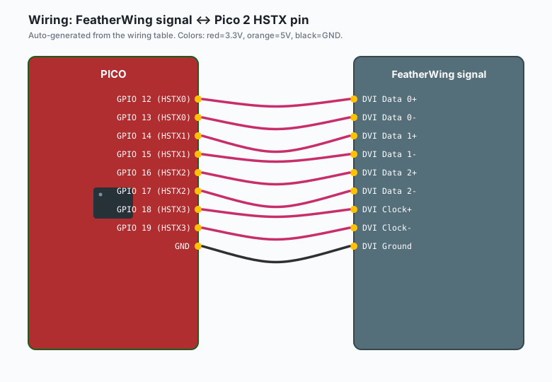
If you are using the Adafruit HSTX-to-DVI FeatherWing, the wiring is: plug the FeatherWing onto the Pico 2. The eight HSTX pads (GPIO 12-19) align with the FeatherWing’s header. There is no soldering if you have header pins on your Pico 2.
| Pico 2 HSTX pin | FeatherWing signal |
|---|---|
GPIO 12 (HSTX0) | DVI Data 0+ |
GPIO 13 (HSTX0) | DVI Data 0- |
GPIO 14 (HSTX1) | DVI Data 1+ |
GPIO 15 (HSTX1) | DVI Data 1- |
GPIO 16 (HSTX2) | DVI Data 2+ |
GPIO 17 (HSTX2) | DVI Data 2- |
GPIO 18 (HSTX3) | DVI Clock+ |
GPIO 19 (HSTX3) | DVI Clock- |
5V (VBUS) | DVI 5V (pin 18 on HDMI) |
GND | DVI Ground |
HDMI carries 5V on pin 18 from the source. The Pico 2 is the source here. The display expects to find 5V on pin 18 to know a source is connected. If you do not wire 5V, some displays will refuse to sync.
If you are wiring to a raw HDMI connector instead of using the FeatherWing, the same mapping applies but you need to twist the +/- pairs and add the 5V and ground. There are DVI connector breakout boards that make this easier; the FeatherWing is the cheapest path.
Install
The HSTX-DVI library lives in the Adafruit MicroPython bundle. In Thonny:
Tools>>Manage Packages- Search for
adafruit_hstx_dvi - Click
Install
If adafruit_hstx_dvi is not in the Thonny package index, you can grab the
.mpy files from the Adafruit MicroPython bundle release on GitHub and
copy them to the Pico 2 filesystem manually (e.g. via the Thonny Files
view, drag and drop to the Pico 2).
The code
# DVI test pattern on a Pico 2 over HSTX
# MicroPython only. Tested with Adafruit HSTX-DVI bundle.

import _thread
import time
from machine import Pin
import HSTX_DVI as dvi

# 640x480p60 is the supported mode.
WIDTH = 640
HEIGHT = 480

# Create the DVI output. The library handles the TMDS encoding and
# the HSTX peripheral setup.
display = dvi.Display(WIDTH, HEIGHT)

# Allocate a framebuffer. The library hands you a 1-bit-per-pixel
# buffer (each byte holds 8 pixels).
framebuffer = display.framebuffer()

# Pin a status LED so we know the script is alive.
led = Pin("LED", Pin.OUT)


def push_pixels():
    """Run on core 1. Just keep the display fed."""
    while True:
        display.show()


def draw_pattern():
    """Run on core 0. Draw a moving test pattern."""
    x = 0
    direction = 1
    while True:
        # Clear the framebuffer.
        for i in range(len(framebuffer)):
            framebuffer[i] = 0

        # Draw a moving vertical bar (8 pixels wide).
        for col in range(x, x + 8):
            for row in range(0, HEIGHT, 2):
                byte_index = (row * WIDTH + col) // 8
                bit_index = 7 - (col % 8)
                framebuffer[byte_index] |= (1 << bit_index)

        x += direction
        if x <= 0 or x >= WIDTH - 8:
            direction = -direction

        led.toggle()
        time.sleep_ms(20)


# Start the display feeder on the second core.
_thread.start_new_thread(push_pixels, ())

# Draw patterns on the main core.
draw_pattern()
The pattern shows up on the monitor as a white vertical bar bouncing left and right. The onboard LED blinks at about 25 Hz so you can see the script is alive.
The CPU overhead you should expect
The video output has to happen every frame, every 16.7 ms, no matter what. That is one core gone for as long as the display is on. If you are running this script and also trying to read sensors, do the sensor reads on the same core as the drawing (core 0). Do not put anything else on core 1. The display feeder on core 1 is not a suggestion; if it falls behind, the display tears or goes black.
The total CPU budget you have left on core 0 is about 30% of one core at 150 MHz, because the HSTX + TMDS encoding eats the rest. That is enough for a game, a UI, or a sensor logger. It is not enough for anything that needs the full M33 core, like heavy DSP.
What you learned
The HSTX peripheral on the RP2350 is the new headline feature. It turns the Pico 2 from a microcontroller into something that can also be a video source, which the original Pico could not do at all. The wiring is simple if you use a FeatherWing, the code is a framebuffer push from one core and your application from the other, and the supported mode is 640x480p60.
The gotcha is that 640x480 is the ceiling, not the floor. If you wanted 1080p, this is not the chip for you. If you wanted a status display, a simple game console, or a debugging readout on a spare monitor, HSTX on the Pico 2 is the cheapest path I have found.
When something breaks
- The monitor says “no signal.” Check the 5V wire. Most HDMI monitors refuse to sync without 5V on pin 18, even for a DVI signal.
- The monitor lights up but the image is corrupt. You are missing one of the data pairs (GPIO 12 through 17). Re-seat the FeatherWing or check your wiring.
- The image tears or stutters. Core 1 is starving. Check that nothing
else is on core 1 (no extra
_thread.start_new_threadcalls, no interrupt handlers running there). - Thonny says
ImportError: no module named 'HSTX_DVI'. The Adafruit HSTX-DVI.mpyfiles are not on the Pico 2 filesystem. Use the Thonny Files view to copy them across. - The Pico 2 reboots when the display comes up. Power supply is too weak. Use a powered USB hub or a 5V supply that can deliver at least 500 mA.
What to build next
- A simple game (e.g. Pong, Snake). 640x480 is enough for both, and the Pico 2 has the headroom for input + drawing + display.
- A status display. Show Wi-Fi signal strength, MQTT message rate, or a sensor readout on a wall monitor.
- The HSTX + PIO pattern, where PIO drives HSTX directly for lower jitter. Covered in the Pico 2 PIO improvements tutorial.
- The Pico MicroPython SDK book (companion) bundles this with the rest of the Pico 2 series.
(these are sample tutorials written for Brian to review on his return. They will not be promoted to “ready” status without his approval.)