ESP32: analog read with the ADC, and why ADC2 is broken on Wi-Fi
Use the ESP32's 12-bit ADC to read a potentiometer or analog sensor. Includes the ADC2 vs Wi-Fi trap and the input-only pin caveat.
The ESP32 has two ADCs (analog-to-digital converters) with about a dozen usable analog input pins. They read voltages from 0 to 3.3V and return a 12-bit value (0 to 4095). That sounds simple. The trap is that ADC2 is shared with the Wi-Fi radio, and you cannot use ADC2 while Wi-Fi is active. This is the single most common “my sensor reads 0 over Wi-Fi” bug.
This tutorial covers both ADCs, the Wi-Fi conflict, the input-only pins, and the calibration that makes your readings mean something.
What you need
- An ESP32 dev board
- A 10k ohm potentiometer (the panel-mount kind with three legs)
- Three jumper wires
Wiring
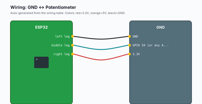
Potentiometer left leg  -- GND
Potentiometer middle leg -- GPIO 34 (or any ADC pin)
Potentiometer right leg  -- 3.3V
GPIO 34 is one of the input-only pins, which makes it a great default for ADC readings. You cannot accidentally drive it as output, so there is no risk of shorting the pot.
Turn the knob all the way one way, you should read 0. All the way the other way, you should read 4095. Halfway, around 2048.
The code
const int POT_PIN = 34;

void setup() {
  Serial.begin(115200);
  analogReadResolution(12);   // 0-4095, default already
}

void loop() {
  int raw = analogRead(POT_PIN);
  Serial.println(raw);
  delay(100);
}
Upload. Open Serial Monitor at 115200 baud. Turn the knob. You should see the value change from 0 to 4095.
What the 4095 actually means
The ESP32’s ADC is 12-bit, which means it divides the 0-3.3V input range into 4096 steps. Each step is about 0.8 mV.
| Reading | Voltage |
|---|---|
| 0 | 0 V |
| 1024 | ~0.83 V |
| 2048 | ~1.65 V |
| 3072 | ~2.48 V |
| 4095 | ~3.3 V |
For real-world use, you almost never care about the raw reading. You care about the voltage, or the percentage, or the sensor-specific value (temperature, light level, etc.). Convert:
float voltage = raw * 3.3 / 4095.0;
float percent = raw / 4095.0 * 100.0;
The Wi-Fi trap (the most common ADC bug)
ADC1 (GPIO 32-39) and ADC2 (GPIO 0, 2, 4, 12-15, 25-27) are different controllers. ADC2 is shared with the Wi-Fi radio. When Wi-Fi is active, ADC2 reads are silently broken: the driver returns 0 or garbage, with no error.
If you are building a Wi-Fi project and your analog sensor reads zero all the time, this is why. The fix is one of two:
- Use ADC1 pins. GPIO 32-39 are ADC1 only. Use those for any sensor that needs to work while Wi-Fi is running.
- Stop Wi-Fi before reading. Not realistic for most projects.
I default to ADC1 (GPIO 32-39) for every analog sensor I wire up. It removes a class of bugs.
The input-only pin caveat
GPIO 32-39 are ADC1, but they are also input-only. You cannot drive them as output. For analog input (which is the use case), this is fine. For anything else, pick a different pin.
The full ADC1 pin list: GPIO 32, 33, 34, 35, 36, 37, 38, 39. On most boards, 37 and 38 are not exposed (they are used for flash on some modules). The practical list is 32, 33, 34, 35, 36, 39.
The accuracy problem
The ESP32’s ADC is notoriously inaccurate. The factory calibration is good to about ±5%, which is fine for “is the knob turned up” but not for “is the temperature 24.3 C or 25.1 C.”
For higher accuracy, the standard fix is a multi-point calibration:
// Take 10 readings, drop the highest and lowest, average the rest
int readSmooth(int pin) {
  const int N = 10;
  int samples[N];
  for (int i = 0; i < N; i++) {
    samples[i] = analogRead(pin);
    delay(5);
  }
  // sort
  for (int i = 0; i < N - 1; i++) {
    for (int j = i + 1; j < N; j++) {
      if (samples[i] > samples[j]) {
        int t = samples[i]; samples[i] = samples[j]; samples[j] = t;
      }
    }
  }
  // average middle 6 (drop 2 highest and 2 lowest)
  long sum = 0;
  for (int i = 2; i < N - 2; i++) sum += samples[i];
  return sum / (N - 4);
}
That gets you ±2% without much extra code.
For higher accuracy, use an external ADC chip like the ADS1115 (16-bit, I2C, about $2). That is in the book Production IoT with ESP32.
Using analogSetAttenuation
The ESP32 ADC can read a wider range if you change the attenuation. By default it reads 0 to about 1.1V accurately. For 0-3.3V, use the 11 dB attenuation:
analogSetPinAttenuation(POT_PIN, ADC_11db); // 0 to ~3.3V full scaleWithout this, readings above about 1V start clipping. If you are reading
a potentiometer connected between GND and 3.3V, you almost certainly
need ADC_11db.
Other options:
ADC_0db: full scale ~1.1V (best accuracy for low voltages)ADC_2_5db: full scale ~1.5VADC_6db: full scale ~2.2VADC_11db: full scale ~3.3V (default for most projects)
Pick the smallest range that covers your signal. Less attenuation = more accuracy but smaller range.
Reading multiple sensors
For multiple analog sensors, just call analogRead on different pins:
const int TEMP_PIN = 34;
const int LIGHT_PIN = 35;

void loop() {
  int tempRaw = analogRead(TEMP_PIN);
  int lightRaw = analogRead(LIGHT_PIN);
  // ...
  delay(100);
}
Each analogRead takes about 30 us. You can read a dozen sensors at
about 3 kHz total.
What you learned
- The ESP32 has 12-bit ADCs (0-4095 for 0-3.3V).
- Use ADC1 pins (GPIO 32-39) when Wi-Fi is active. ADC2 is broken with Wi-Fi.
- The 12-bit ADC is good to about ±5% out of the box. Multi-sample averaging gets you to ±2%. For higher accuracy, use an external ADC.
analogSetPinAttenuation(pin, ADC_11db)is what you want for any sensor that outputs 0-3.3V.
When something breaks
- Readings are 0 with Wi-Fi running. You are using ADC2 pins. Move to GPIO 32-39.
- Readings max out at about 1100-1300. You forgot to set the
attenuation. Add
analogSetPinAttenuation. - Readings are noisy. Add the multi-sample averaging pattern above, or use a capacitor on the analog input (10-100 nF to GND).
- Readings drift over temperature. The ESP32’s internal reference voltage drifts with chip temperature. For sensor readings that need to be stable across temperature changes, use the external ADC.
What to build next
- The BME280 sensor tutorial uses I2C, not analog, but the wiring patterns are similar and the project is the most common first sensor.
- The deep sleep tutorial uses ADC readings as a trigger: only wake up the Wi-Fi radio when the sensor crosses a threshold.
- The book Production IoT with ESP32 covers the ADS1115 external ADC in depth.